Davy's (2nd) CNC Mill
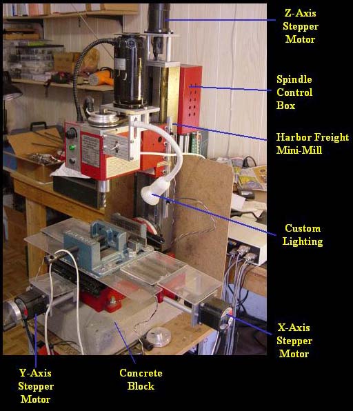
My second CNC mill is shown in the picture below. This one took about 1 year to complete from start to finish. It's got some major improvements and advantages over my first mill.
Figure 1. Completed CNC Mini Mill
After using my first CNC mill for a while, I eventually became somewhat unhappy with its limitations. My first CNC mill was constructed mostly of 6061 aluminum alloy, which made it insufficiently rigid to whack off large amounts of material at one time. This meant that I could not use it for "roughing". For small parts, this was fine, but for large work pieces, it took forever to get anything machined. Sometimes, it would take days. So, I got tired of waiting forever every time I wanted a make a part. This led me to the inescapable conclusion that I needed to build a second CNC mill.
Enter The Chinese Mini Mill
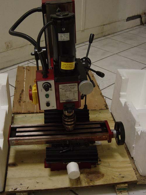
Figure 2. Harbor Freight Chinese Mill (Item # 44991) Fresh out of the Box.
My first CNC took about 3 years to complete. Looking back, I was definitely crazy to attempt building it from scratch. So naturally, I did not want to spend that kind of time building the second one. To get a head start on the mechanics, I decided to buy a Chinese made mini mill from Harbor Freight. The same mill can be bought from Grizzly, Cummins and many other retailers. I decided to buy a mill instead of building one because it was cheaper to buy than to build. It also saved me a lot of time since the mechanicals was mostly completed from the get go. All it needed were some minor modifications. Furthermore, the mini mill was sturdy enough for taking deeper cuts.
What are Those Chinese Manufacturers Smoking?!

Figure 3. Very Strange Hand Wheel Rollover Value! Why 0.0625" per revolution?!
After taking the mill out of the box, the first thing I noticed was the strange rollover values on the hand wheel dials. The hand wheels did not rollover in powers of 10 as implemented in most standard mills. Instead one revolution is equivalent to 0.0625 inches! This means that those Chinese designers chose a 16-pitch (16 Threads Per Inch) lead screw! What were they thinking?!
Anyone who's ever even casually used a mill knows that each revolution of the hand wheels ought to translate by a power of 10. Otherwise, it becomes very difficult to keep track of your position without a DRO (digital read out).
Needless to say, the first thing I did was swap out the lead screw. I replaced the screws with ACME 1/2-10 precision screws. This made keeping track of X, Y, Z positions much more convenient.
Stepper Motors

Figure 3. Z-Axis Stepper Motor
Next, I began installing the X, Y, and Z stepper motors. All steppers are bipolar driven, and have dual shafts for mounting optical encoders and hand wheels to their rear shafts. I used the encoder feedback for implementing a software DRO, and the hand wheels for manual jog controls.
Spindle Upgrade
The mini mill came with a spindle that had a high and low gear setting. I hated these gears. The gears were very noisy and hideously unreliable. Somebody in quality control at the Chinese factory needs to get their heads screwed on straight. After just a few uses, one of the gears got crunched. Argghh!!
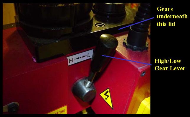
Figure 4. Original Spindle with High/Low Gear Controls
So, I eventually decided I had had enough. I took it apart, and very quickly discovered why the gears were so easy to break. The main gears were made of plastic! I assume those Chinese manufacturers were trying to save money. Needless to say, I needed to rebuild this spindle.

Figure 5. Modifications and Upgrades to the Spindle
I started by getting rid of all the gears, and replaced them with a pulley system. Even if the gears were robust and reliable, I just couldn't stand the noise anymore. I designed the pulley system with a high and low gear ratio setting, and also a belt tension adjuster. This allowed some belt length variation. Not all vendors will make the same belt to the same exact size. So, some slop needs to be accounted for.

Figure 6. Spindle Electronics Modifications
Next, I modified the spindle electronics so that I could control and sense the RPM from my controller box. I did this by adding a solid-state relay for controlling power on/off, and replacing the manual POT (potentiometer) with a digital POT.

Figure 7. Spindle Electronics POT Input Diverted to Digital POT
The digital POT was on my controller board. This way, the microcontroller on my board can command the digital POT to set a resistance values, which are fed directly to the spindle box. This way, I was able to control the RPM remotely from my controller board.
Limit/Homing Switches
Next, I added limit switches to all 3 linear axes. I used photointerrupters for these switches. These are basically slotted through-beam sensors. On one side of the slot, you have an IR (infrared) emitter. On the other side, you have a photodetector. When the beam is blocked mechanically, the output signal will switch from high-to-low, or low-to-high, depending on how I hook it up.

Figure 8. X-Axis Limit Switches

Figure 9. Y-Axis Limit Switches

Figure 10. Z-Axis Limit Switches
USB CNC Controller
The final task in building my CNC mini mill was designing the controller. The picture below shows my completed controller.
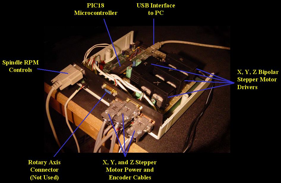
Figure 11. USB Mini Mill CNC Controller
The controller has USB connectivity, Microchip's PIC18F series microcontroller, independent "plug and play" bipolar stepper drivers, closed-loop encoder feedback, and spindle RPM controls. A picture of one of those "plug and play" bipolar stepper drivers is shown below. My original intent was to sell the controller and stepper drivers separately. In the end, I decided against commercialization. (I've got something else in mind)
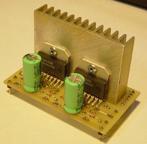
Figure 12. Plug and Play Stepper Driver
The biggest challenge in getting the controller to work was by far the USB connectivity. From my experiences with my first CNC mill, I hated RS-232. The data throughput was way too slow. So, I was very motivated to get rid of the RS-232 interface. This was NOT an easy task. Not having a background in software or electrical engineering, I needed to get up speed quickly on the USB protocol.
I began this task by reading a book called USB Design by Example, by John Hyde. I didn't find this book very useful. The examples were vague. By the time I finished this book, all I could do was write code for HID (human interface device) devices. These are devices such as mice, keyboard, etc that directly interface the PC with human beings. The maximum throughput on HID devices were highly limited. If I recall correctly, HID devices were limited to a maximum 100 packets per second, and each packet was 8 bytes.
Up to this point, I had purposely avoided reading the official USB specification. The document was too large, and too intimidating. Eventually, I decided that's exactly what I needed to do. Fortunately, I didn't need to read most of it. Only the protocol section was pertinent to me. I didn't need to bother with the electrical signaling or mechanical connectors. The electrical signaling was already taken care of by the USB transceiver chip. I chose Philips Semiconductor's PDIUSBD12 transceiver chip. The rights to this chip was eventually bought by some other company. At that time Philips also had some good application notes for the PDIUSBD12 chip. So, in the end, what really helped me gain enough understanding of the USB protocol were these app notes.
CNC Test Run
I was very ambitious in my first attempt at a test run. I had never machined anything truly 3-dimensional, and I wanted to try.
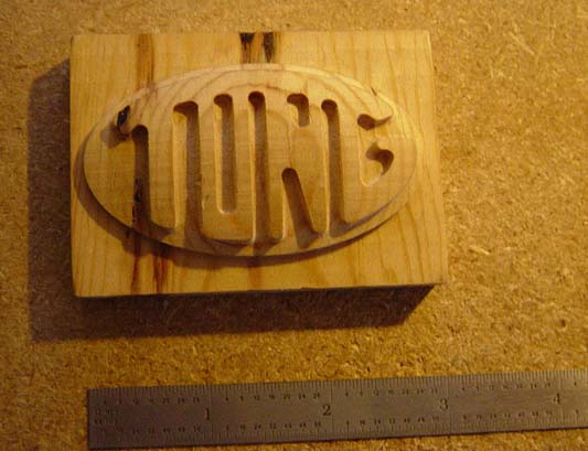
Figure 13. Three-Dimensional Dome-Shaped Part Fabricated by CNC Mini Mill
The picture above shows the final result of my attempts at 3D surface machining. The emblem shown in the picture has "Tong" engraved on a dome-shaped surface. I used Mastercam to generate the G&M codes. It took about 5 hours to make this part. I basically clicked on the "run" button and left my machine running all night.
That picture actually shows my third attempt at 3D machining. I had to kill my first two runs due to some unforeseen software bugs that really needed to be fixed right away.