Zettl Group Page |
Research Highlights
|
|
|
|
|
|
Watching Atoms Move at the Edge of a 2D Crystal
Ç. Ö. Girit, J. C. Meyer, R. Erni, M. D. Rossell, C. Kisielowski, L. Yang, C.-H. Park, M. F. Crommie, M. L. Cohen, S. G. Louie, A. ZettlDepartment of Physics, University of California at Berkeley
Materials Sciences Division, Lawrence Berkeley National Laboratory
National Center for Electron Microscopy, Lawrence Berkeley National Laboratory
Berkeley, CA 94720, U.S.A.
The following media files are intended for public access, and may be reproduced as long as proper credit is given: "Courtesy Zettl Research Group, Lawrence Berkeley National Laboratory and University of California at Berkeley." All rights reserved © 2009.
Introduction
Can we see individual atoms move around in real time? Can we look at a crystal and see the bonds break and form as atoms reposition themselves? With the advent of aberration-corrected transmission electron microscopes (TEM) such as TEAM 0.5, the answer to these questions is yes. Not only do these microscopes allow us to resolve every single atom in a sample, they can do so at meaningful (short) timescales. For the first time, we can make live recordings of the dynamics of atoms.
An ideal system in which to study atomic dynamics is graphene, a single sheet of graphite. This atomic layer of carbon atoms, rubbed off the end of a pencil tip, can be suspended on a grid for observation in the TEAM microscope. The pristine hexagonal carbon lattice is interrupted by a hole, intentionally produced by prolonged irradiation by the TEAM electron beam. Atoms at the edge of the hole are gradually ejected by electrons from the beam and the size of the hole grows (movie below). Atoms that have lost their neighbors are highly volatile, and move around rapidly to find a stable configuration. By analyzing the growth of the hole and the atomic rearrangement, we conclude that the zigzag configuration is the most stable one for an open edge of graphene.
To substantiate our observations, we modeled the atomic dynamics of the hole with a kinetic monte carlo method. This is a technique in which each atom is given a probability, determined by ab-initio calculations, to be either ejected from the lattice, inserted, or to migrate to a neighboring site. The simulation starts with a pre-defined hole in the graphene sheet, and like in the experimental recording, as the hole grows the atoms along the edge reconfigure into more stable arrangements. The zigzag configuration, after many cycles, dominates over the armchair one. Both experiment and simulation concur. We propose a simple mechanism for the improved stability of the zigzag configuration at the hole edge.
Videos
If you use any of the following videos, please include the credit "Courtesy Zettl Research Group, Lawrence Berkeley National Laboratory and University of California at Berkeley."
|
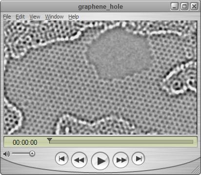
Movie taken with the TEAM 0.5 microscope of the growth of a hole and atomic edge reconstruction in a graphene sheet. Graphene is a single atomic layer of carbon atoms arranged in a hexagonal lattice. An electron beam focused to spot on a graphene sample can blow out the exposed carbon atoms, producing a hole in the sheet. Graphene hole movie (QuickTime 4.5 MB) |

|
To simulate the atomic dynamics of the hole in graphene, a kinetic monte carlo method was used. The probabilities for atomic migration, insertion, and ejection are determined by ab-initio calculation. The simulation starts with a predefined hole in a graphene sheet. As it proceeds, the hole grows and the atoms along the edge rearrange themselves. The zigzag configuration is found to dominate the armchair one. If you use the following simulation, please include the credit "Courtesy M.L. Cohen, S.G. Louie, and A. Zettl research groups, Lawrence Berkeley National Laboratory and University of California at Berkeley." Simulated graphene hole movie made using XCrySDen. (QuickTime 1.6 MB) |
Still Images
If you use any of the following images, please include the credit "Courtesy Zettl Research Group, Lawrence Berkeley National Laboratory and University of California at Berkeley."

|
TEM grid with 1�m holes. The holes with a greenish hue have been spanned with a single graphene layer. Graphene sheet (high res.) (TIFF 69.4 MB) |

|
Here is the first frame from the movie of the graphene hole taken with the TEAM 0.5 microscope (see above). Graphene hole, frame 1 (high res.) (PNG 4.1 MB) |

|
Simulated image of a hole in a graphene sheet produced using QuteMol. Graphene hole 3D Sim. (low res. variant 1) |

|
3D rendering of graphene hole image made with Gwyddion. |

|
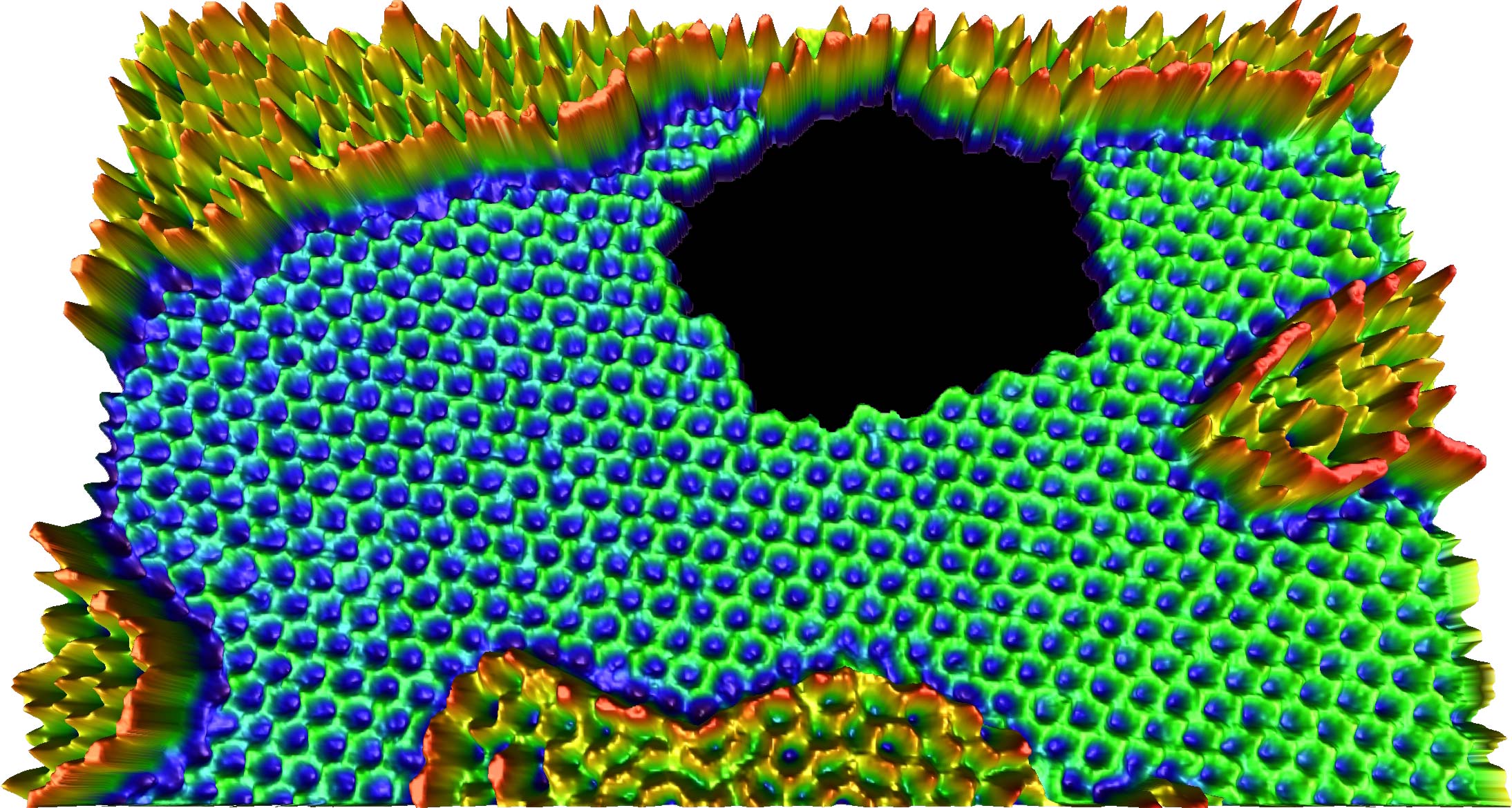
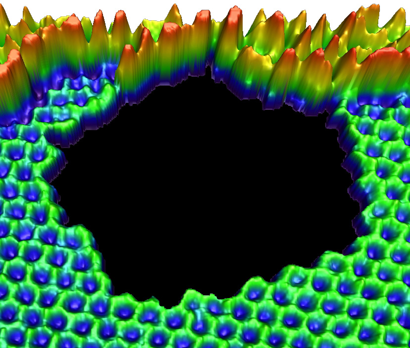
3D rendering of graphene hole TEAM 0.5 image made with WSxM. |
|
3D rendering of graphene hole TEAM 0.5 image made with WSxM. Graphene hole 3D (high res.)(PNG 3.30 MB) |

|
Schematic of zigzag (red) and armchair (blue) edge configurations. The position of the edge is indicated by the white dashed line. While both configurations appear in the TEAM 0.5 movie, above, zigzag edges are more stable under electron beam irradiation and they eventually predominate. Edge schematic (med res.) (PNG 56 KB) |

|
Schematic of edge stability. Removal of an atom at an armchair edge (blue, top) leaves behind an isolated atom, whereas removal from a zigzag edge (red, bottom) does not. Edge stability schematic (med res.) (PNG 49 KB) |
Acknowledgements
The National Center for Electron Microscopy is supported by the Department of Energy under contract DE-AC02-05CH11231. The TEAM project is supported by the Department of Energy, Office of Science, Office of Basic Energy Sciences. Ç.G. and A.Z. were supported by the Director, Office of Energy Research, Office of Basic Energy Sciences, Materials Sciences, and Engineering Division, of the U.S. Department of Energy under contract DE-AC02-05CH11231, through the sp2-bonded nanostructures program. L.Y., C.-H.P., M.L.C, and S.G.L. were supported by the National Science Foundation and by the Director, Office of Science, Office of Basic Energy Science, Division of Material Sciences and Engineering, U.S. Department of Energy.
External Links
The original Science article published March 27, 2009, the cover image, and the Supplementary Online Material.
National Center for Electron Microscopy and the TEAM 0.5 microscope.
Last modified: Thu Mar 27 12:00:00 Pacific Daylight Time 2009